Understanding semi-log graph for Bode plot can seem daunting, but with a little explanation, it becomes much easier to grasp. This type of graph is commonly used in engineering and science to represent frequency response of a system.
Essentially, a semi-log graph has one axis that is linear and another axis that is logarithmic. The linear axis typically represents the magnitude of a system’s response, while the logarithmic axis represents the frequency of the input signal.

Semi-Log Graph For Bode Plot
Semi-Log Graph For Bode Plot
When plotting a Bode plot on a semi-log graph, you can easily visualize how a system responds to different frequencies. The logarithmic scale allows for a wide range of frequencies to be represented in a compact space, making it easier to analyze the system’s behavior.
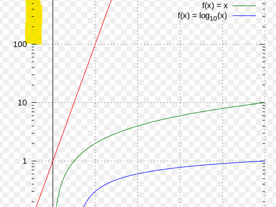
On a semi-log graph, each division on the logarithmic axis represents a different order of magnitude. This allows you to see how the system responds to frequencies that vary greatly in magnitude, from very low to very high frequencies.
By looking at the Bode plot on a semi-log graph, you can quickly identify key characteristics of a system, such as its bandwidth, gain margin, and phase margin. This information is crucial for designing and analyzing control systems in various engineering applications.
In conclusion, understanding how to read a semi-log graph for Bode plot is an essential skill for engineers and scientists. By visualizing the frequency response of a system on a semi-log graph, you can gain valuable insights into its behavior and make informed decisions when designing and optimizing control systems.

PDF Introduction To Bode Plot

Graphing Functions How Does The Log Axis On A Semilog Plot Work Mathematics Stack Exchange